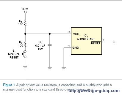
简单的增加一对电阻、一个电容、一个按键开关转换标准 三端复位管理器 为 手动复位
增加手动复位功能通常需要手动复位输入的新电路。但是通过增加一对低值电阻,标准三端复位管理器能够实现普遍应用。电路如图1所示,从按下手动复位按钮时刻起,确保纯净的![]() 信号。当复位按钮被触发,VCC电压降到复位管理器最小复位限(S1按下时,VCC电压为R1/R2的电压分压)。这个动作导致复位管理器
信号。当复位按钮被触发,VCC电压降到复位管理器最小复位限(S1按下时,VCC电压为R1/R2的电压分压)。这个动作导致复位管理器![]() 输出有效。松开S1,VCC电压恢复到高于最大复位限,其中
输出有效。松开S1,VCC电压恢复到高于最大复位限,其中![]() 一直有效到复位管理器完成time-out时间段。
一直有效到复位管理器完成time-out时间段。

S1不被按下时,复位管理器供电电流和![]() 输出装填会导致R2电压降的情况。对绝大多数复位管理器,最大供电电流为50 &mICro;A。对绝大多数设计,
输出装填会导致R2电压降的情况。对绝大多数复位管理器,最大供电电流为50 &mICro;A。对绝大多数设计,![]() 输出经过一或两个 CMOS 输入,每个输入需要10 µA。带两个CMOS的设备接到
输出经过一或两个 CMOS 输入,每个输入需要10 µA。带两个CMOS的设备接到![]() ,经过R2的总电流将为(2×10 µA)+50 µA=70 µA。经过R2的电压降为复位管理器复位限电压加上70 µA×100Ω=7 mV的电压和。
,经过R2的总电流将为(2×10 µA)+50 µA=70 µA。经过R2的电压降为复位管理器复位限电压加上70 µA×100Ω=7 mV的电压和。
考虑替换方式来选择R1, R2和C1的值。旁路电容C1的值应该足够低
S1触发时,电流流过R1 和R2。在图1的电路中,S1触发时电流为3.3V/(100Ω+100Ω)=16.5 mA。电流大小满足线性功率系统,但是不适合电池供电系统。通过增大R1值的方法减小电流,确保复位管理器VCC低于最小复位限。也可以增大R2,但是会导致电压降增加和瞬时响应减缓。提醒注意的是,增加手动复位电流只在手动复位有效时发生,典型的系统电流下降在![]() 有效时才会出现。
有效时才会出现。
附英文原文
Add a manual reset to a standard three-PIN-reset supervisor
Simply adding a couple of resistors, a caPACitor, and a pushbutton switch transforms a standard three-pin-reset supervisor into a manual reset.
Derek Vanditmars, Delta Controls, Surrey, BC, CANada; Edited by Charles H Small and Brad Thompson -- EDN, 4/12/2007
Adding a manual reset to a design usually involves designing in a new part with a manual-reset input. But, by adding a couple of low-value resistors, a standard three-pin-reset supervisor can work in most applications. The circuit in Figure 1 ensures a clean signal during and after you have pressed the manual-reset button. When you activate the manual-reset button, the supply voltage drops below the reset supervisor’s minimum reset threshold because of the R1/R2 voltage divider formed when S1 is active. This action causes the reset supervisor to activate its output. When you release S1, the supply voltage returns to above the reset-supervisor maximum-reset threshold, and remains active for the time-out period of the reset supervisor.