·支路H1,电缆颜色SW,连接插脚9,电缆颜色RT/SW
·支路H2,电缆颜色BR,连接插脚11,电缆颜色BR/SW
仅限于带有Basis组合仪表的E39/E53车型:将支路H1和H2铺设到组合仪表上如下通过迷你连接器K连接到26极SW插头X11175,如图14所示。

·支路H1,电缆颜色SW,连接插脚21,电缆颜色GN/BL
·支路H2,电缆颜色BR,连接插脚1,电缆颜色BR/SW
仅限于带有High组合仪表的E39/E53车型:将支路H1和H2铺设到组合仪表上如下通过迷你连接器K连接到18极SW插头X16,如图15所示。
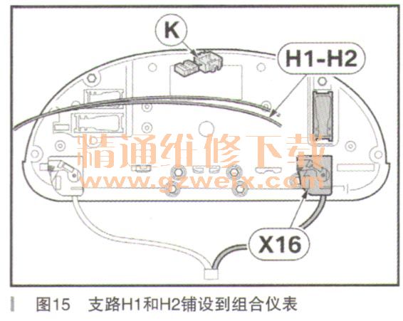
·支路Hl,电缆颜色SW,连接插脚17,电缆颜色GN/BL
·支路H2,电缆颜色BR,连接插脚1,电缆颜色BR/SW
仅适用于E6x车型:将支路H1和H2铺设到CAS A149上,如下通过迷你连接器K连接到54极SW插头X10318,如图16所示。
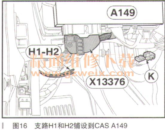
·支路H1,电缆颜色SW,连接插脚8,电缆颜色GN/GR
·支路H2,电缆颜色BR,连接插脚12,电缆颜色BR/SW
仅限于除F15/F16之外的F1x车型:将支路H1和H2铺设到CAS A16上如下通过迷你连接器K连接插头A16*1B,如图17所示。
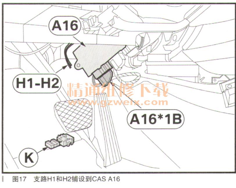
·支路H1,电缆颜色SW,连接插脚7,电缆颜色GN/GE
·支路H2,电缆颜色BR,连接插脚25,电缆颜色BR
仅限于FOx车型:将支路H1和H2铺设到CAS A16上,如下通过迷你连接器K连接插头A16*1B,如图18所示。
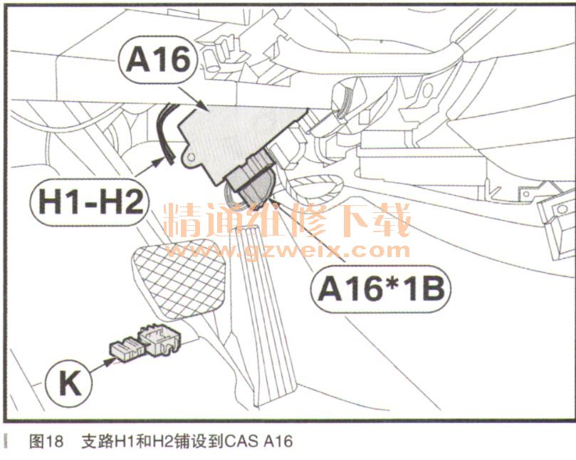
·支路H1,电缆颜色SW,连接插脚1,电缆颜色GN/GE
·支路H2,电缆颜色BR,连接插脚25,电缆颜色BR
仅限2006年9月之前的E83车型:将支路H1和H2铺设到指示灯模块A3上,如下通过迷你连接器K连接到54极SW插头X12,如图19所示。

上一页 [1] [2] [3] [4] 下一页


