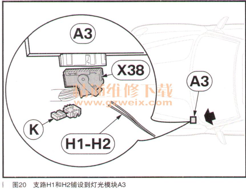
·支路H1,电缆颜色SW,连接插脚巧,电缆颜色GN/BL
·支路H2,电缆颜色BR,连接插脚31,电缆颜色BR/SW
仅限2006年9月之后的E83车型:将支路H1和H2铺设到灯光模块A3上,如下通过迷你连接器K连接到76极NT插头X38,如图20所示。
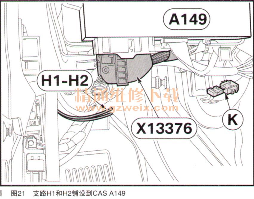
·支路H1,电缆颜色SW,连接插脚31,电缆颜色GN/BL
·支路H2,电缆颜色BR,连接插脚57,电缆颜色BR/SW
仅限于E70/E71车型:将支路H1和H2铺设到CAS A149上,如下通过迷你连接器K连接到54极SW插头X13376,如图21所示。
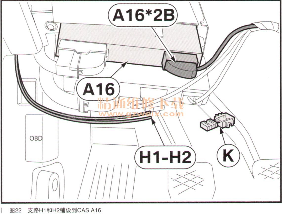
支路H1,电缆颜色SW,连接插脚14,电缆颜色GN/WS
支路H2,电缆颜色BR,连接插脚25,电缆颜色BR
仅限于F25/F26车型:将支路H1和H2铺设到CAS A16上,如下通过迷你连接器K连接到26极NT插头A16*2B,如图22所示。
·支路H1,电缆颜色SW,连接插脚24,电缆颜色GN/BL
·支路H2,电缆颜色BR,连接插脚22,电缆颜色BR/SW
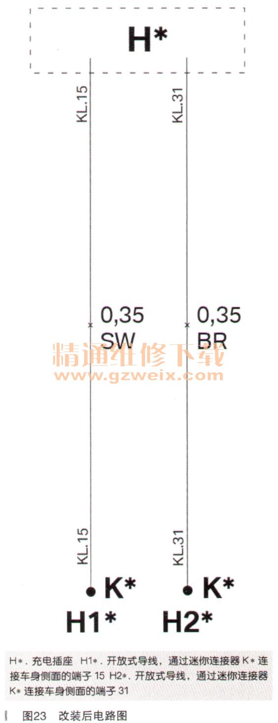
7.电路图
改装后电路图如图23所示。
上一页 [1] [2] [3] [4]


