7.3 摄像头电路
1.主摄像头电路
在iPhone 5手机中,主摄像头信号通过MIPI信号总线与应用处理器进行通信,数据信号通过I2C总线进行通信,主摄像头电路如图62所示。

主摄像头电路框图如图63所示。

2.辅助摄像头电路
iPhone 5手机辅助摄像头电路如图64所示。

iPhone 5手机中I2C总线由iPhone 4S的排感L8改为现在的独立电感FL14、FL15、FL12,主要是减小线路之间的干扰。iPhone 5手机MIPI线与iPhone 4S相对比,由原来的4个分立的0Ω电阻改为共模电感L35、L39,主要是让信号传输更加稳定。iPhone 5手机辅助摄像头电路框图如图65所示。

3. 闪关灯电路
照相机闪光灯电路U17如图66所示。

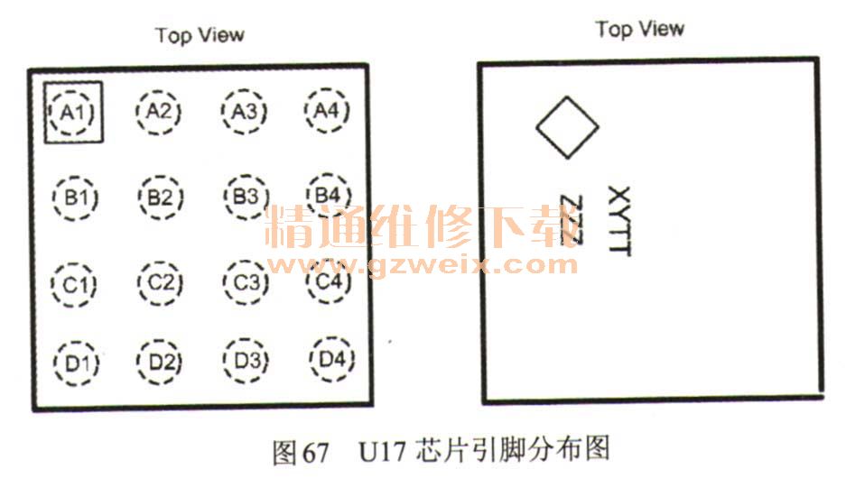
照相机闪灯电路U17芯片引脚分布图如图67所示。
上一页 [1] [2] [3] [4] [5] [6] [7] [8] [9] [10] [11] 下一页


